THE MASTER SHEET
Each design has a Master Sheet, reached with the Goto Master Sheet command at the top of the Template menu. The contents of this sheet are drawn on all sheets in the design, providing a method for displaying a single sheet style throughout a design.
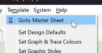
The Goto Master Sheet command on the Template menu
The following points relating to the master sheet are worthy of note:
- While objects on the master sheet are visible on every sheet in the design they can only be edited or deleted by returning to the master sheet.
- 2D graphics, imported images and scripts are the objects that belong on the master sheet, and they are the only object types that survive a paste or an import onto it. If you paste or import a mixed selection, the graphics, images and scripts are brought in and everything else is discarded; if nothing in the selection qualifies, you are told that the clipboard holds nothing that can be pasted to the master sheet.
- If you change the sheet size on a given sheet such that it is no longer the same as the sheet size of the master sheet then the master sheet is suppressed across all sheets, both on screen and in printed output (it would be pointless at best to have a master sheet of A4 size showing on an A3 sheet, for example).
- If you change the size of the master sheet you will be prompted to change the size of all existing sheets to match. Take care over this on a design that already has circuitry on it: reducing the sheet size can leave parts on other sheets outside the work area, where you cannot reach them.
The software does not prevent you placing components on the master sheet, but you must not do so. Components on the master sheet are not part of the design's netlisted circuitry, and connectivity will break. Keep the master sheet to graphics, images and scripts, and draw your circuit on the design sheets.
Two commands are unavailable while the master sheet is the current sheet: Edit Sheet Properties and Remove/Delete Sheet, neither of which has any meaning for it. Automatic annotation is also suppressed, so anything you place there is not given a reference. There is no command to leave the master sheet as such; Goto Previous Sheet and Goto Next Sheet both return you to the first sheet of the design.
Rendering the Master Sheet
If you do not see your graphics on the design sheets although they are present on the master sheet, go to the Template menu, select Set Design Defaults and check the Render Master Sheet? box.
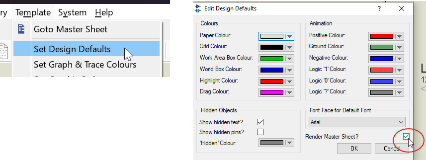
The Render Master Sheet? option on the Edit Design Defaults dialogue form
Render Master Sheet? is a per-user application setting rather than a property of the design, so unlike every other control on that dialogue form it is not carried in a .DTF template you share. A colleague opening your template gets their own setting.
Sheet Borders and Grid References
The sheet border belongs on the master sheet, so that it appears on every sheet in the design. If you add GRID markers to that border, the row and column references they define are available to the Component Placement Report, which uses them to say whereabouts on the sheet each part sits.
Grid markers are looked for on the current sheet first and on the master sheet second, so markers placed on an individual sheet take precedence over those on the master sheet.
The procedure for adding grid markers to a border is given under Component Placement Report.
See Also:
Templates Tutorial, for a walkthrough of creating and modifying design templates including editing the master sheet.
Edit Design Defaults, for the controls on that dialogue form.